Polyphonic pickup, amplitude
repository: polypu
At this point, the already weaving path of the project starts to branch even more than it already could have. Considering the options, there is one experiment that stands out to me, one that I’ve been curious about ever since I realized the footprint could accomodate it. In the past, I’ve built prototype pickups with a single coil arrangement, but variations of a double coil, humbucking arrangement are also quite common in guitars. I haven’t considered it for long before, as the design space back then was a bit different, with a different set of pressures acting on the construction. Before, I was trying to decrease cross-talk between channels while being less concerned with noise, and now the requirement on the noise floor became the more pressing one.
Looking at the noise contribution of the coils and their arrangement also feels methodical in the sense that it targets the source of the signal path: the point where the fluctuating magnetic field of the magnetized string induces a fluctuating voltage in the turns of the coil. However, the coil will also pick up ambient fields, which - from the perspective of the pickup - we can consider to be noise (more specifically, interference).
Broadly speaking, adding a second coil with matching parameters on a parallel axis and in a different physical position allows it to generate noise that closely matches that of the first one and therefore can interfere destructively with it. In addition, it could either be used to generate a (roughly) matching signal that can constructively interfere with the signal from the first coil, or it could produce no signal, acting as a dummy coil. Before our experiments can begin, we’ll need a way to measure the noise floor of an arrangement of coils, though.
Amplitude measurement
The previous measurements allowed us to look at a signal in both the time and frequency domains, and although they were useful for understanding the shape of the signal, they are a bit too low-level as metrics of evaluation. To express the noise floor as a one-dimensional value, let’s add another measurement for the average amplitude.
The amplitude measurement will take a number of samples, and divide them evenly into windows. Within each window, it will calculate the absolute average of the sample values, normalize that, and convert that magnitude into decibels relative to overload (dBov), and emit that series as a result.
After summing the absolute values, normalization is done through dividing the sum by the length of the window to yield a value spanning the input range, then dividing it by the maximum value of that range to yield a normalized value from zero to one.
double normalized = sumabs / (double)window / (double)INT16_MAX;We express the ratio as an amplitude ratio, or root-power quantity.
return 20. * log(normalized) / log(10.);However, this output will be skewed by any DC offset the input signal might have. In analog-to-digital conversion, there will often be some offset from the half-point of the input range, and this offset can be easier to eliminate in software than in hardware. In our case, even the smallest offsets will affect our ability to measure the low AC amplitudes corresponding to the noise floor.
Initially, I thought I’d just pass the signal through a high-pass Butterworth filter, as I already had an implementation for it that used Q16.16 fixed-point. Later, I realized it might be better to use simpler mathematics, to make the accuracy of the results easier to verify. The simplest I could think of was to calculate the average value of the captured length, round it to the nearest integer, and to subtract it point-wise before averaging the absolute (full-wave rectified) signal.

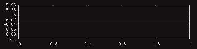
To check, let’s measure the amplitude of a synthesized half-scale square wave, with a period of 64 samples, and a DC offset of an eighth of the full range. The below measurement had a capture length of 1024 samples, and a window length of 512, yielding two points. The average AC amplitude of such a signal should be -6.02dBov, as it is the half-scale version of the square wave at the threshold of overload.
Output bandwidth limitations
Previously, while creating measurements for the pickup, it seemed enough to yield often enough to allow the tinyusb task to transmit the output, freeing space in the buffer we would like to add new output to. Since then, I have encountered the same unreliability in the output stream, and decided to take another look.
The problem was that I wasn’t using any real flow control, which
meant that whenever the pickup produced data faster than the endpoint
could carry it and the fifo could hold it, it would inevitably end up
getting lost if execution proceeded. Luckily, tinyusb provides the
tud_cdc_n_write_available function, which returns the
number of bytes that the associated output fifo could receive, and which
can be used block execution when necessary.
created
modified